What Raspberry PI 3+ GPIO Pins should I avoid using for general purposes? I know about pin 28 (GPIO 1), which hats and daughter boards use…
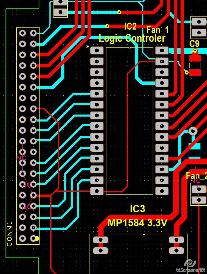
Here is a screenshot of the PCB. As you can see I need 14 GPIO signals. The logic controller is an Adafruit itsy bitsy 32u4 - 3v. I want to ensure this will work before sending the board to my PCB house. The yellow dot is pin 1.
As far as I can tell, 14 GPIO pins are classified as “general purpose”, although of them also support additional functionality: 4, 5, 6, 12, 13, 16, 17, 18, 22, 23, 24, 25, 26, 27.
first, the “Adafruit itsy bitsy 32u4 - 3v” is not a microcontroller but a microcontroller board
derived from an Atmega32u4 chip. Your screenshot implies that it is a singular pin-socket microcontroller.
Start by creating a schematic that includes your board with the added Adafruit itsy bitsy 32u4 - 3v. Methodically audit each and every pin from the Adafruit itsy bitsy 32u4 - 3v board that is connected to your board (carefully tracing each pin from the microcontroller board to your board’s connector CONN1). You will have to review the Adafruit itsy bitsy 32u4 - 3v pinout from its user guide or provided schematic.
The Adafruit itsy bitsy 32u4 - 3v pinouts can be found here:
Ensure that you provide a proper grounding plane so that no eddie currents are generated. This will ensure that ground points at different locations are not at different potentials. Are you going to be using analog signals as well? i.e., ADC measurements, op-amps, ampliefiers, etc. in your board? If so, you will want to create two grounding planes separated by (generally) a zero ohm resistor. A digital ground and an analog ground.
First, I think my first post was misleading, and wish to apologize for my bad wording.
Here is what I trying to do.
I am working on a stepper motor controller. I am using a Raspberry PI 3+ running a GUI Python app. When the user has selected the mode/options they want they select the execute button. When execute is selected the GUI code decodes the user-selected options into logic controller commands by setting the GPIO pins on or off. Once the GPIO pins have been set it sets the ‘RUN’ pin high. When the logic controller sees the run pin is high, the controller sets the ‘BUSY’ pin high telling the PI it is busy running a task. Then it reads it’s GIOP pins and decodes them. Once decoded the logic controller controls the stepper motor to do the required motion (step, direction, etc.). Once the task is complete the controller sets the busy pin low, telling PI the task is complete and awaiting for the next task. Then the controller waits for PI to reset the run pin to low, once it returns to low it awaits for the next task.
Here is the GUI code that tells the controller to run the task
def Run_Task():

# First start the LED flashing thread
	Stop_LED_Flashing = False
	Ready_LED_Flashing = Thread(Set_Ready_LED_Flashing)
	Ready_LED_Flashing.daemon = True
	Ready_LED_Flashing.start()
# Debug Statement
	print("Telling controller to run the task")
# Tell controller to execute the task
	GPIO.output(Run_Pin, True)

# Wait until stepper controller has started the task
	while( !GPIO,input(Busy_Pin) ):
		pass
# Now wait until the stepper controller has finished the task
	while(GPIO,input(Busy_Pin)):
		pass

# Control has finished so return the Run pin to false to tell the controller the PI has
	GPIO.output(Run_Pin, False)
	Stop_LED_Flashing = True

# Debug Statement
	print("Controller completed task Retuning")
I had to use the logic controller because Python can not provide the required microsecond timing for proper stepper motor operation (shortes pules is around 22 mico seconds or appx 40 KHertz).
The supper thin PCB tracks in the screenshot is the GND signal ( to keep PCB CAD software happy) which disappears when the GND planes are poured (on both top and bottom layers).
is incorrect because 1) it has ! instead of not (this is Python, not C) and 2) it has a comma instead of a dot (and you repeat this one error a little later too).
You bring up PI (I interpret this as the PI feedback loop controller). This generates (calculates) the new control signal based on the error (reference - feedback). The feedback is the signal measurement and should be as clean as possible. If you don’t use a separate ground plane for the feedback signal, you may: 1.) introduce noise 2.) introduce a bias offset. This may degrade the quality of the feedback signal and thus corrupting the output from the PI controller and by extension, potentially have bad or inconsistent good motor control. This would be the analog part (circuit).
Update:
If you are not using the ADC to measure the feedback signal, then this implies you are operating in open-loop. If this is the case, then you don’t need a separate analog ground.