Sending 5 bytes over Serial Port

Hi Paul,

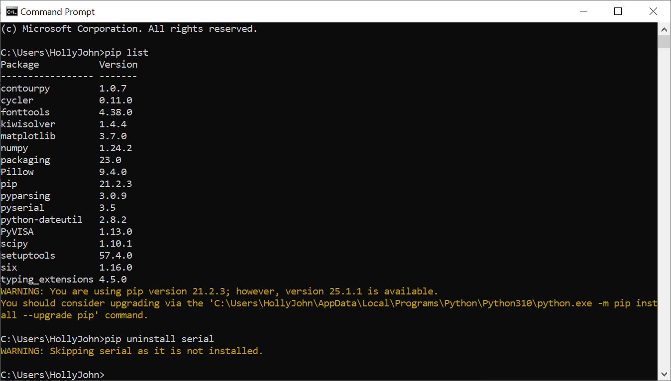
Here is what is installed. The installation was done with an outdated version of pip as it barked as you can see in the return:

I didn’t run the code you supplied as I have the computer on something else right now, but when the original 3 commands were sent, the “CAT” annunciator would have flashed once for each successful command. It did not.

Thanks,
John

Ok, just upgrade it since a newer version is available. Type the following to upgrade pip:

python -m pip install --upgrade pip

Ok, good. You don’t have serial installed.

Ok, once you get back from the 4th, we’ll see what the o-scope observations are.

The commands and responses are binary, maybe with some BCD, not text encoded as UTF-8, so decoding a response as though it’s UTF-8 is likely only to cause a UnicodeDecodeError.

Also, .readline() will make it wait for a newline (0x0A), but it’s not text ending with a newline, and .strip() assumes that there’s whitespace, but there isn’t, because it’s not text.

On Windows, it’s recommended that you use the Python Launcher py:

py -m pip install --upgrade pip

Thanks Matthew.

I haven’t the time today to devote to anything Ham Radio or anything non-home-related. When the smoke clears and before I go through the O-scope routine (I’m still learning how to record the event and then display it against another!), I’ll update the pip per Paul and the base software. It has been a couple years since it was initially installed…

Thanks for the heads-up.
John

Hello All,

I hope everyone had a happy and safe 4th!

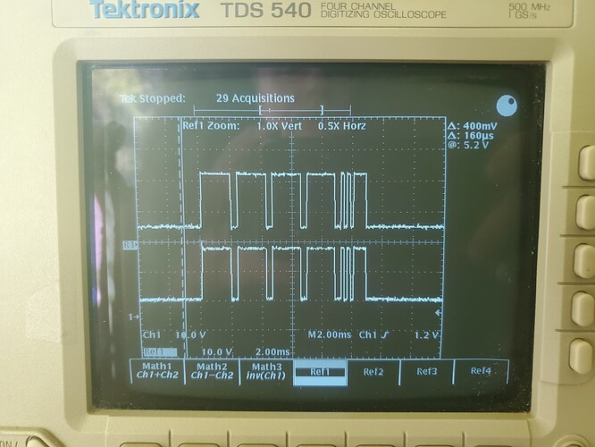
I gave myself (and you!) a week off to hopefully get a new footing. I dragged the O-Scope off the bench and connected it to the RS-232 connector. Sorry for the photo - the GPIB does not work on this machine, so I had no way to supply a Hardcopy…

The top trace is the code that works. The lower is the first LabVIEW I did. I would have supplied a Python output but PyScripter is locked in Debug Mode and before I close out the app, I thought I would ask if there is a way to get out (the Stop buttons do nothing) before I close the app.

The command sent is 0x00, 0x00, 0x00, 0x00, 0x85. Both records look the same and the Nulls are very evident, but:

Where is the Start Bit??? I am triggering on a rising edge. I expected to see at least part of the start bit.

The last byte is supposed to be 0x85 (10000101). I don’t think that is what I am displaying.

I left the cursor off to the left side so you can see that a Mark or Space is ~160us. The last Mark is 800us. The last byte is only 1.63ms - ~ 200us shorter than the Null bytes. Ugh.

Thoughts?

I appreciate it!
John

Hello,

that is not the \0x85 message byte. Remember that you are sending in total 5 messages in series - back-to-back. When you set your oscilloscope to capture on rising edge, it will capture the very first message sent. This is why you need to increase the time/div setting to capture ALL of them in one sweep - and not just the very first one. Recall that what you are sending is:

msg = ['\x00', '\x00', '\x00', '\x00', '\x85']

What it appears that you have captured is the first message (though even that does not appear as first message since that would imply 11 bits - 8 message bits, 2 stop bits, and a no parity bit per configuration). Note that the message \x85 is sent last. This is why in one of my last posts I suggested to set your times per division setting on the oscilloscope high (~50 ms to start; you need to play around with it for your particular test, however). Note that your screen is sectioned into 10 sections. Therefore, if you have the time/div set to 50 ms, it will take 10 x 0.050 s to complete one sweep. If you increase the setting, it will increase linearly as a function of the time/div setting - so have patience as it completes the sweep.

From the photo that you provided, the time/div is set to 2 ms. This is much too small to also capture the other 4 messages, with the last one being the encode \x85 message . You also have to take into account the dead time between messages. This is another reason to set your time/div setting relatively high.

So, to capture ALL of the messages, you have to take into account (at a minimum), 4 dead times between messages (represented by the blue lines), and 5 x 11 bits (represented by the red rectangles). Here is a rough sketch.

Those 2 traces do look identical, so I don’t see why the radio would respond to one but not the other.

The traces show the complete message, all 5 bytes plus their start and stop bits.

The level is usually low (“_”).

The start bit is high (“¯”).

The data bits are from least to most significant bit, with high for logic 0 and low for logic 1. (I don’t know why they’re that way round, but whatever…)

The stop bits are low.

Thus for 00 00 00 00 85 it’s:

____¯¯¯¯¯¯¯¯¯__¯¯¯¯¯¯¯¯¯__¯¯¯¯¯¯¯¯¯__¯¯¯¯¯¯¯¯¯__¯_¯_¯¯¯¯_______
....<00000000>><00000000>><00000000>><00000000>><10100001>>....

< = start bit
> = stop bit

At 4800 baud, the 55 bits (5 packets, each of 11 bits) require 55/4800 secs, assuming no gaps between the packets. The divisions on the scope are 2ms apart, so you’d expect the messages to last about 5.7 divisions, again assuming no gaps, which they do.

1 Like

Hi Gentlemen,

I was being stupid on the start bit - yes, it is lost in the 0x00 byte but evident in the last byte sent - duh. I said the Mark/Space was 160us, but a day late and dollar short John did the math this AM and realized it should be 200us. The rise/fall time of each bit is sluggish and when I measure a Space instead of a Mark, it is 200us. Double duh.

I’m pretty sure I captured at various horizontal sweep speeds but maybe not. Sure looks chopped-off. I injured my strong hand wrist yesterday evening and cannot use my hand. Tripple duh. It might take a while to perform another capture as it takes two hands. In the mean time, I’ll read and reread your posts about this and hopefully capture in my head, the subtleties.

Thanks, guys. You have no idea how much appreciation I have for your patience and interest.

Gee, typing with one left finger is tough…
J

I read both replies carefully, then looked at what I had captured. Paul, I am quite sure I captured all 5 bytes and then some. I was studying the screenshots I took. There are 5 bytes each with two Stop bits. I did not take into account endianess and now that I have, I can see that the last byte is 0x85 - just the words are reversed.

I am quite stumped here. I half-hoped there would be a trailing character or the byte timing is off or somethig! But the two captures appear exactly the same as Matthew pointed-out.. It seems the code is correct and there is something else amiss.

Have you ever seen a case where a DTE is selective as in this case. It seems a stupid question (I have many) but what is left?

John

Hi @jmltinc,

yes, I believe you sent the message correctly per @MRAB’s clear explanation. When I glanced at the screenshot, per our previous chat, I thought that you were going to go ahead and introduce some deadtime between each individual byte message sent. I was expecting something similar (though the deadtime was exaggerated a bit in the sketch) to the sketch that I provided - this is why it kind of threw me off a bit at first glance - wasn’t expecting them clumped together.

As a simple test, can you add 5 ms of dead time between messages to see if it behaves differently.

time.sleep(5)  # Place at the end of the for loop statement

Is a handshake expected from the transceiver back to your Python program - a message as a confirmation that the message was received? Can you increase the time setting of the oscilloscope first with the known working Labview / C code to verify (or not)? Increase the time setting to ~10 ms / div and re-capture/re-test - to see if a message is observed trailing your initial transmitted message.

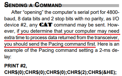
May I refer you to page 91 of the manual?

“If you send a parameter that is out of range for the intended function, or not among the specified legal values for that function, the MARK-V FT-1000MP should do nothing. Therefore, you may wish to alternate your sending regular command or command groups with the Read Flags or short-form Update commands, allowing the transceiver to let the computer know if everything sent so far has been accepted and acted upon as expected.”

I can see nothing in the manual that suggests that there’s any kind of handshaking.

From what I can tell, you just send a command and some of those commands return a response. You’re not told whether the command has been successful; you just have to read the status periodically via the appropriate command(s).

But, then, I only know what the manual says.

Early on, I tried the delay you suggested Paul; adjusting it to see if there was a sweet spot, with no results.

Matthew, your interpretation of the manual is quite correct. If you send a command then read the buffer for a reply, there is none - the radio just does what it is supposed to. The only time there is something in the buffer is when you are looking at the Status Flags. Of course I have no working software for that.

For the record, the only code that worked was the exe made of QT/C++ that copied VFO-A to VFO-B. Any LabVIEW nor Python version worked - that is about a dozen different efforts.

Well, we beat a dead horse pretty well, didn’t we? I am thankful and honored you two put so much effort in trying to make this work. There is a positive out of this too. I learned some Python!

Thanks guys. Very much!

John

For what its worth, can you try this (from page 95):

Which are two messages back to back:

msg1 = ['\x00', '\x00', '\x00', '\x02', '\x0e']  # First message sent - added the "2" in the 4th byte for 2 ms (but modify per system needs if necessary)
msg2 = ['\x00', '\x00', '\x00', '\x00', '\x85']  # Second message sent

You may have to add some delay between messages, however. That value, I do not know. Try different values to test.

Thanks, Paul.

I believe at some point I did send a Pace command (just for the heck of it) with 0 results. The Pace command is really to slow the transmission of radio data so the computers of 1999 could keep-up if they had a lot of overhead or really slow CPU’s.

John

Ok, sorry we couldn’t help. Was hoping we could.

:confused:

From what I found, the FT-1000 doesn’t have any kind of flow control, but the FT-2000 does.

So, as a final attempt, here’s a simple GUI that lets you test with or without flow control:

# A simple GUI for testing talking to a FT-1000MP_Mark-V radio via the CAT/serial port.
#
from serial import Serial, SerialException
from tkinter.messagebox import showerror
import tkinter as tk

# The port to use.
DEFAULT_PORT = "COM5"

class App(tk.Tk):
    def __init__(self):
        super().__init__()
        self.title("Radio GUI")

        # Add a frame for the buttons.
        button_frame = tk.Frame(self)
        button_frame.pack(side=tk.TOP, fill=tk.X)

        # Add a "Port" entry.
        tk.Label(button_frame, text="Port:").pack(side=tk.LEFT)
        self.port_var = tk.StringVar(value=DEFAULT_PORT)
        self.port_entry = tk.Entry(button_frame, width=10, textvariable=self.port_var)
        self.port_entry.pack(side=tk.LEFT)

        # Add the flow control checkbox.
        tk.Label(button_frame, text="Flow control:").pack(side=tk.LEFT)
        self.flow_control_var = tk.BooleanVar(value=False)
        self.flow_control_checkbox = tk.Checkbutton(button_frame, variable=self.flow_control_var, onvalue=True, offvalue=False)
        self.flow_control_checkbox.pack(side=tk.LEFT)

        # Add the "Connect" button.
        self.connect_button = tk.Button(button_frame, text="Connect", padx=5, pady=5, command=self.on_connect)
        self.connect_button.pack(side=tk.LEFT)

        # Add the "Clear log" button.
        self.clear_log_button = tk.Button(button_frame, text="Clear log", padx=5, pady=5, command=self.on_clear_log)
        self.clear_log_button.pack(side=tk.LEFT)

        # Add the "A -> B" button.
        self.copy_vfo_a_button = tk.Button(button_frame, text="A -> B", padx=5, pady=5, command=lambda: self.send("A -> B", bytes.fromhex("00 00 00 00 85")))
        self.copy_vfo_a_button.pack(side=tk.LEFT)

        # Add the "Read status flags" button.
        self.read_status_flags_button = tk.Button(button_frame, text="Read status flags", padx=5, pady=5, command=lambda: self.send("Read status flags", bytes.fromhex("00 00 00 00 FA")))
        self.read_status_flags_button.pack(side=tk.LEFT)

        # Add a frame to display the log.
        response_frame = tk.Frame(self)
        response_frame.pack(side=tk.TOP, fill=tk.BOTH, expand=True)

        # Add a title label for the log frame.
        tk.Label(response_frame, text="Log").pack(side=tk.TOP)

        # Add a listbox with a scrollbar to display the log.
        self.log_listbox = tk.Listbox(response_frame)
        self.log_listbox.pack(side=tk.LEFT, fill=tk.BOTH, expand=True)
        scrollbar = tk.Scrollbar(response_frame, orient=tk.VERTICAL, command=self.log_listbox.yview)
        scrollbar.pack(side=tk.RIGHT, fill=tk.Y)
        self.log_listbox.configure(yscrollcommand=scrollbar.set)

        # The serial port and response buffer.
        self.serial_port = None
        self.response_buffer = b""

        # Disable the buttons initially.
        self.enable_buttons(False)

        self.send_buffer = b""

        # Periodically check for a response.
        self.on_tick()

    def on_tick(self):
        if self.serial_port is not None:
            if self.send_buffer:
                self.serial_port.send(self.send_buffer)
                self.send_buffer = b""

            # Read any (additional) response from the serial port. We want to append to the current response, if any.
            if self.response_buffer:
                self.log_listbox.delete(tk.END)

            self.response_buffer += self.serial_port.read(self.serial_port.in_waiting)

            if self.response_buffer:
                self.log_listbox.insert(tk.END, self.response_buffer.hex(" ").upper())

        # Schedule the next check or send.
        self.after(200, self.on_tick)

    def on_connect(self):
        if self.serial_port is None:
            # Try to connect to the serial port.
            try:
                self.serial_port = Serial(port=self.port_var.get(), baudrate=4800, parity="N", stopbits=2, bytesize=8, rtscts=self.flow_control_var.get())
            except SerialException as ex:
                showerror(self.title(), str(ex))
            else:
                # We connected successfully, so enable the buttons.
                self.enable_buttons(True)
                self.connect_button["text"] = "Disconnect"
        else:
            # Disconnect from the serial port and disable the buttons.
            self.serial_port.close()
            self.serial_port = None
            self.connect_button["text"] = "Connect"
            self.enable_buttons(False)

    def on_clear_log(self):
        self.log_listbox.delete(0, tk.END)
        self.response_buffer = b""

    def send(self, description, data):
        if self.serial_port is None:
            return

        # We're going to send a command, so log the action and clear the response buffer.
        self.log_listbox.insert(tk.END, f"[{description}]")
        self.response_buffer = b""

        try:
            self.serial_port.write(data)
            self.serial_port.flush()
        except SerialException as ex:
            showerror(self.title(), str(ex))
            self.serial_port.close()
            self.serial_port = None
            self.connect_button["text"] = "Connect"
            self.enable_buttons(False)

    def enable_buttons(self, enable):
        # These must be disabled when connected.
        new_state = tk.DISABLED if enable else tk.NORMAL
        self.port_entry["state"] = new_state
        self.flow_control_checkbox["state"] = new_state

        # These must be enabled when connected.
        new_state = tk.NORMAL if enable else tk.DISABLED
        self.copy_vfo_a_button["state"] = new_state
        self.read_status_flags_button["state"] = new_state

App().mainloop()
Hey Fellas,

If I was in any kind of team, I would want you both as my teammates. You got my back and don’t give up. WOW!

Paul, no need to feel bad - I learned something - some Python!

Matthew, I didn’t try to run your code as I can’t use a mouse yet, but the manual shows the RTS and CTS lines as NA on the connector. Additionally, I was able to read the working exe using None as the Flow Control for the Read app.

Once my wrist gets to where I can mouse, lift and probe, I was going to see what the UART spits out to the processor in the radio. This was a last gasp for me since I am reasonably convinced our codes are the same as the working code - BUT - I had a revelation. Actually, it has been bothering me since I first discovered it before I decided to try Python and wrote this wonderful forum.

I am pretty sure I mentioned it (if I didn’t - I am truly sorry), but when you first open the working exe, it requires you to select a Port. Then the GUI changes to the A to B button. The first click does not work (the radio does not respond) on this click but responds every click thereafter. Further, I cannot connect using LabVIEW nor Python to this port until the exe is closed.

In all one-shot versions of LV and Python code, the Port is closed after the command is sent. I think there is a good chance the exe has an IF statement to check whether the ports is open or not when the button is clicked and THE PORT STAYS OPEN UNTIL THE FORM IS CLOSED! (why the radio balks at the first command is another story).

Matthew, I cannot mouse through the code you sent that has the popup. I think the Connect button turns into a Disconnect button which means it works like the exe. If that is the case my revelation is bunk. Can you expound, please?

John

The manual says that the RTS and CTS pins are N/A, but, considering that all else failed, I thought that there’s no harm in just trying it.

On the matter of the exe, does it send the code on the first click, or is it the radio that isn’t responding to the first code?

The GUI opens the serial port when you click Connect and closes the serial port when you click Disconnect. It’s the same button, it’s just the caption that changes.

From the sound of it, it does seem that the exe is keeping the serial port open until it quits, but it’s not clear when the serial port is actually opened.

If you start the exe, not click a button, and then run the other code, but the latter can’t connect, then the serial port being opened immediately.

On the other hand, if you start the exe, not click a button, and then run the other code, and the latter can connect, then the serial port is being opened only when it’s first needed.

I expect the first scenario is the case.

The manual says that the RTS and CTS pins are N/A, but, considering that all else failed, I thought that there’s no harm in just trying it.

Early-on, I did add Flow Control and tried all possible combinations with no results. In any event, the Read code I wrote uses None for Flow Control and returns the data.

On the matter of the exe, does it send the code on the first click, or is it the radio that isn’t responding to the first code?

Yes, the Read app returns the correct 5 bytes on first click. The radio won’t respond on the initial command.

The GUI opens the serial port when you click Connect and closes the serial port when you click Disconnect. It’s the same button, it’s just the caption that changes.

I was afraid of that…

I am able to mouse some today (left-handed mousing is a no-go) and ran the Write operation inside a loop so I could send multiple commands without closing the port (LV). A loop back and Read just before closing the ports shows the command was sent. The Read app confirms that.

From the sound of it, it does seem that the exe is keeping the serial port open until it quits, but it’s not clear when the serial port is actually opened.

If you start the exe, not click a button, and then run the other code, but the latter can’t connect, then the serial port being opened immediately.

On the other hand, if you start the exe, not click a button, and then run the other code, and the latter can connect, then the serial port is being opened only when it’s first needed.

I expect the first scenario is the case.

You are correct. As soon as you select the port it is opened. QT’s equivalent of a Form.Close event must close the port.

Too bad the ‘Revelation’ was not the trouble. I don’t believe - even if the radio is jazzed-up, that it can discern flavors of code.

Now that I can mouse a little bit, I will play with the various Python codes - who knows…

Thanks,
John

Hello @jmltinc,

going back to the o-scope screenshot that you provided, the idle state voltage appears to be ~+5V with a maximum voltage of ~+21.5V (both positive - note that you have it set to 10V/div). RS-232 requires both positive and negative voltage levels. The standard dictates that you have positive level for a logic 0 and a negative level for a logic 1.

Based on this, I think that you need an RS-232 voltage level converter. I suspect the large voltage level swings are to make it immune to noise, and IR drops - in case its deployed in industrial settings and to account for the potential use of long cables, which wouldn’t be out of the norm.

Here is a fair explanation:

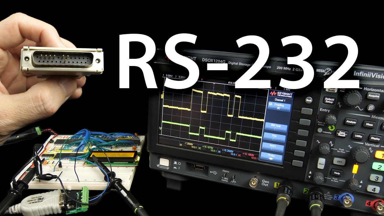
Here is a video that might help. You can go to the ~4:45 minute mark where he starts explaining the voltage level swing requirements:

I think that this should solve your issue.